|
|
|
This is my attempt to describe how the PC versions of the SAGA images were formed. Note I have taken this information from only a few games (the few PC ones I've been able to find). If you have any PC versions of the other SAGA games I would like to see them so I can ensure that my routines work on all of them. The games I used are:
Basic formatThe PC games are stored directly on a disc using separate files for each major part of the game. These include the compiled interpreter, the SAGA+ datafile and the images. The images have a file name which includes the name and number of the image, for example B001.PAK - this indicates that it is used to overlay onto the room images and that it is image number 1. The indicators are:
Fortunately the file format is the same for each type of image. The files are drawn on a basic CGA screen. This limits the graphics to only using 4 colours: black, cyan, magenta and white. The screen resolution is 320 x 200. Assuming that origin is at the top left of the screen. The area used for images starts at (24,0) and extends to (204,158). This leaves a miniscule space of screen of 4 lines for text descriptions! The Header
The Graphics ChunkThis is followed by the graphics chunk. The graphics are rended by a simple RLE encoding scheme: Get byte If byte has bit 8 set plot next byte (byte & 0x7f) times Else plot the next byte (byte & 0x7f) times Endif Note, due to the low amount of colours, the graphics data is set at 2 bits per pixel with the bit values being:
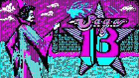
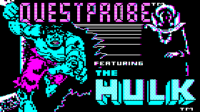
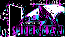
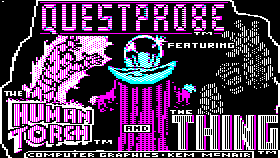
One final thing to note about how the plotting: the y-axis is interlaced; so row 0 is followed by row 2; then row 158 is followed by row 1. Also, note the offset and lengths are signified in block offsets including the margins Complex images are formed by overlay other images over a basic image. For example, the inventory in Sorcerer is formed by plotting the image R033 and then overlaying the B images (e.g. B009, B023) over the top for each object in the inventory. Size FlagThere is an extra form of compression, over the normal RLE encoding. On some images (most of those in QP3!) the size of the horizontal pixels are doubled. This quarters the storage size of the image; but lowers the quality. This is signified by setting either or both 0x0d or 0x0e in the header to the value 0xff. To render this simply double plot all X co-ordinates. CodeThe code is relatively simple to extract the images from the originals. Here is the C code I was using to test my extraction routines. It uses the allegro library and will save the image with the input filename, but with a .bmp extension. ImagesThe extracted images:
|


